Abstract
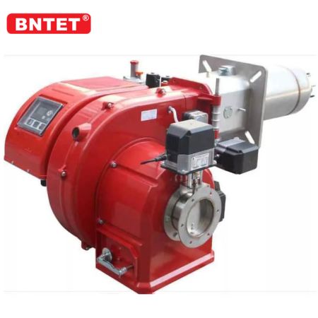
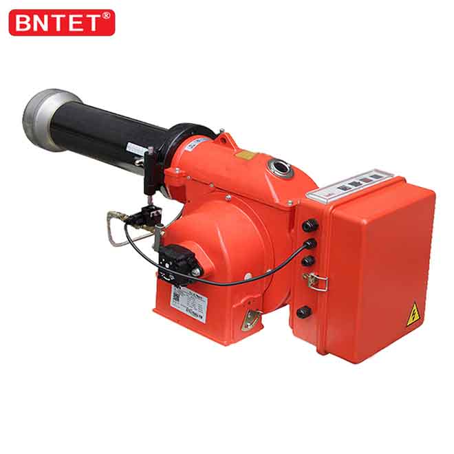
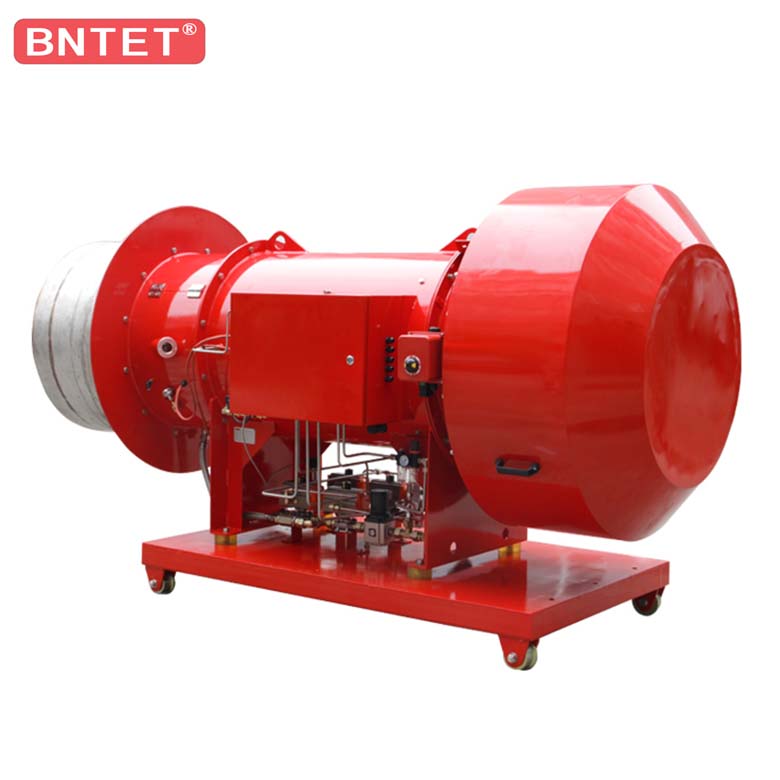
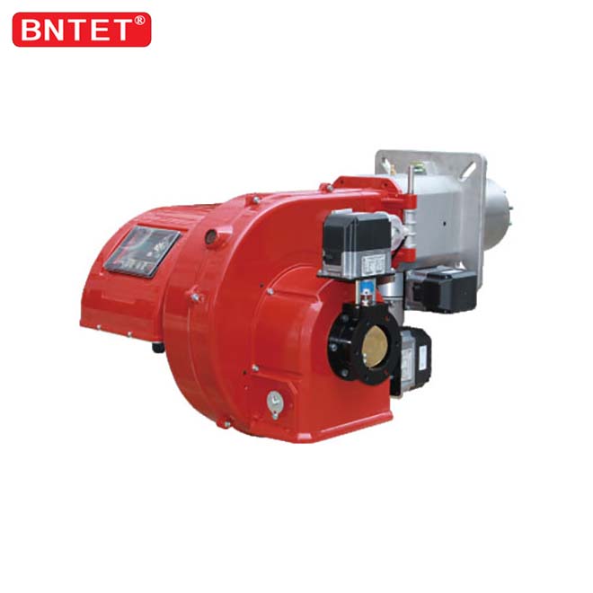
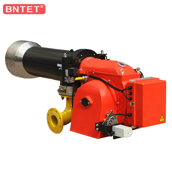
In large-scale industrial heating, thermal fluid heaters, rotary kilns, and steam boiler applications, relying on a singular fuel supply exposes manufacturing facilities to commodity price volatility and seasonal pipeline curtailments[2, 5]. Modern dual fuel industrial burners resolve these operational vulnerabilities by integrating gaseous fuels (natural gas, LPG, biogas) and liquid fuels (light diesel, biodiesel, heavy residual oil) onto a single burner chassis[1, 4]. Engineered by Bona Thermal Energy (BNTET), this technical article reviews the coaxial fuel train architecture, comparative nozzle atomization mechanics, digital combustion management controls, and automated fuel-switching safety interlocks essential for reliable thermal uptime[3, 6].
1. Coaxial Aerodynamic Architecture of Dual Fuel Burners
The design challenge of dual fuel industrial burners lies in matching the disparate mixing kinetics, ignition delays, and flame lengths of gaseous and liquid hydrocarbons within a shared aerodynamic throat[1, 7]:
                           Dual Fuel Burner Head
                                     │
       ┌─────────────────────────────┴─────────────────────────────┐
       ▼                                                           ▼
Channel A: Gas Injection Ring                      Channel B: Retractable Liquid Fuel Lance
(High-Velocity Radial Spuds)                       (Centerline Atomizer & Diffuser Swirler)
Immediate Premixing / Staged Annulus               High-Pressure Hydraulic or Air/Steam Atomized
       │                                                           │
       └─────────────────────────────┬─────────────────────────────┘
                                     │
                                     ▼
                     Shared Combustion Air Swirl Diffuser
                    (Creates Stable Internal Recirculation Zone)
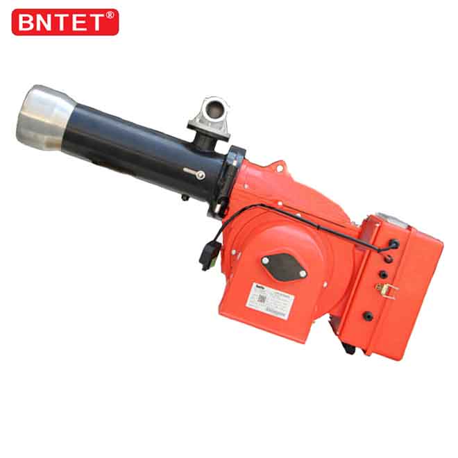
Gaseous Delivery Array: High-velocity gas spuds or annular gas rings discharge fuel radially into the swirling incoming combustion air. Precision drillings generate intense shear zones that enhance localized turbulent diffusion before entering the core flame envelope[4].
Axial Liquid Lance: The oil gun is mounted precisely along the central axis. Because droplet trajectory and momentum differ from gas jets, an internal mechanical retract mechanism or purge air shield protects idle oil nozzles from radiant baking, coking, and nozzle orifice plugging while operating in dedicated gas mode[2].
Common Swirl Diffuser: Aerodynamic swirl vanes generate a toroid-shaped Internal Recirculation Zone (IRZ). The reverse vortex brings hot intermediate combustion products back toward the root of the nozzle, stabilizing ignition for both gaseous and liquid fuel regimes[1, 7].
2. Liquid Fuel Atomization Dynamics: Pressure Jet vs. Twin-Fluid Media
To achieve rapid, complete droplet evaporation and suppress unburned hydrocarbon (UHC) formation, the liquid fuel must be broken into a fine polydisperse spray characterized by a low Sauter Mean Diameter ($SMD < 50\,\mu\text{m}$)[3, 7]:
| Atomization Method | Operational Principle | Primary Fuel Viscosity Target | Turn-Down Ratio | Air / Steam Utility Consumption |
| Mechanical Pressure Jet | High fuel pressure ($18 - 30\text{ bar}$) converted to kinetic energy through swirl slots | Low viscosity ($< 12\text{ cSt}$ at nozzle; Diesel/Gas Oil) | $1:3 - 1:4$ | Zero atomizing medium required[7] |
| Air-Assisted (Twin-Fluid) | High-velocity compressed air ($4 - 7\text{ bar}$) shears low-velocity fuel streams | Medium to high viscosity ($< 35\text{ cSt}$; Heavy/Waste Oil) | $1:6 - 1:10$ | $0.08 - 0.15\text{ kg air / kg fuel}$[3] |
| Steam-Assisted (Twin-Fluid) | Saturated dry steam ($5 - 8\text{ bar}$) transfers shear momentum and promotes thermal cracking | Heavy residual oils, bunker grades ($< 45\text{ cSt}$) | $1:6 - 1:8$ | $0.10 - 0.20\text{ kg steam / kg fuel}$[2] |
3. Automated Fuel-Switching Sequences and Safety Interlocks
Modern multi-megawatt dual fuel industrial burners rely on electronic fuel-air ratio control (microprocessor burner management systems such as Siemens LMV or Lamtec) to govern rapid, fail-safe fuel handovers without flame extinction[4, 6]:
On-the-Fly vs. Cold Switchover: While cold switchovers involve scheduled boiler shutdown and mechanical purge routines, automated on-the-fly changeovers allow boilers to transition from natural gas to light oil under load. The controller ramps down the active fuel control valve while simultaneously igniting and opening the secondary fuel line to preserve continuous steam pressure[6].
Dual Flame Safeguard Monitoring: Gas and oil flames display differing spectral emission peaks. Gas flames emit weak visible light with strong ultraviolet (UV) emissions (310 nm OH* band), whereas heavy oil flames radiate intense yellow/infrared (IR) signatures from luminous incandescent soot particles. Dual fuel installations utilize dual-sensor flame detectors (UV tube plus IR flicker detector) to prevent false flame-out trips[1, 4].
Automatic Nitrogen / Compressed Air Post-Purge: Following transition away from oil firing, pneumatic purge valves immediately flush the residual liquid fuel out of the burner lance into an isolated drain tank. This prevents thermal radiation from boiling stagnant oil inside the nozzle tip and causing carbon build-up[2].
4. Key Engineering Advantages of Deploying Dual Fuel Burners
Strategic Energy Cost Arbitrage: Operators can dynamically switch between natural gas and liquid fuels depending on spot commodity market pricing, leveraging the lowest cost per gigajoule (GJ) available[5].
Interruptible Gas Tariff Eligibility: Industrial facilities with dual-fuel capability qualify for discounted "interruptible" natural gas delivery contracts from gas utilities, capturing significant annual operational savings while maintaining complete operational redundancy with on-site diesel or heavy oil reserves[6].
Process Continuity and Zero Downtime: For continuous processes such as district heating, hospital utility boilers, asphalt batching plants, and metallurgical rotary kilns, the ability to switch fuels in minutes prevents costly process shutdowns caused by supply pipeline pressure drops[3].
5. Summary and Equipment Sourcing
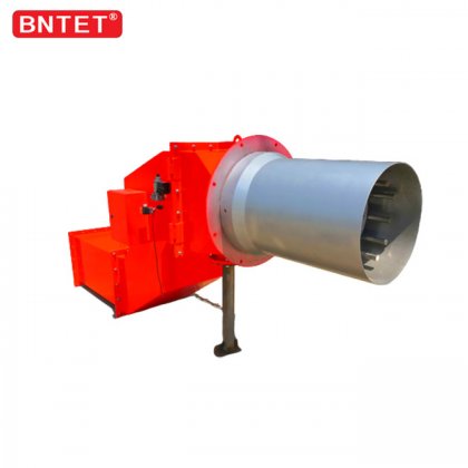
Implementing heavy-duty dual fuel industrial burners provides the ultimate thermal insurance for critical steam and heating infrastructure[2, 5]. Bona Thermal Energy (BNTET) manufactures monoblock and split-type dual fuel burners from 0.5 MW up to 35 MW, featuring precision digital cam controls, low-NOx staged aerodynamics, and robust atomization assemblies compatible with natural gas, LPG, light diesel, heavy fuel oil, and alternative bio-oils.
For burner sizing curves, retrofit evaluations, and dual-fuel system schematics, please
References
Turns, S. R. (2012). An Introduction to Combustion: Concepts and Applications (3rd ed.). McGraw-Hill Education.
https://www.mheducation.com/highered/product/1259025946.html Baukal, C. E. (Ed.). (2013). The John Zink Hamworthy Combustion Handbook: Fundamentals and Applications (2nd ed., Vol. 1). CRC Press / Taylor & Francis Group.
https://doi.org/10.1201/b15110 Lefebvre, A. H., & McDonell, V. G. (2017). Atomization and Sprays (2nd ed.). CRC Press / Taylor & Francis Group.
https://doi.org/10.1201/9781315120911 Warnatz, J., Maas, U., & Kohler, R. W. (2006). Combustion: Physical and Chemical Fundamentals, Modeling and Simulation, Experiments, Pollutant Formation (4th ed.). Springer-Verlag Berlin Heidelberg.
https://doi.org/10.1007/978-3-540-45363-5 Glassman, I., Yetter, R. A., & Glumac, N. G. (2014). Combustion (5th ed.). Academic Press / Elsevier.
https://doi.org/10.1016/C2011-0-05856-7 National Fire Protection Association (NFPA). (2023). NFPA 85: Boiler and Combustion Systems Hazards Code. National Fire Protection Association, Quincy, MA.
https://www.nfpa.org/codes-and-standards/85-standard-development/85 Bayvel, L., & Orzechowski, Z. (1993). Liquid Atomization. Taylor & Francis / CRC Press.
https://doi.org/10.1201/9781482276947